Hardware Assembly

Attention
The installation steps are expected to take 30~60 minutes, please note the following:
1.When fixing the screws, do not tighten the screws vigorously to avoid sliding wire;
2.When fixing the board, please tighten them separately after the four copper pillars or screws are fixed;
Install the robot chassis
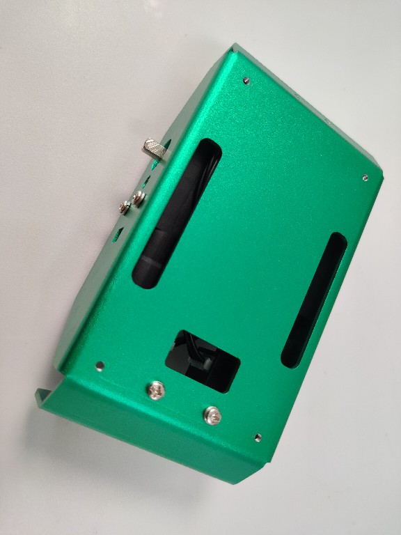
Install the universal wheels:
Materials required:
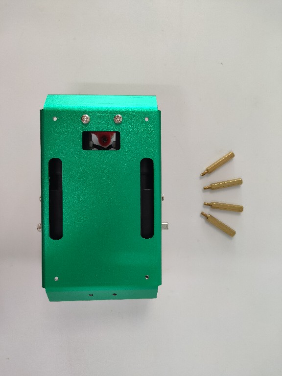
(1) Install the universal wheel to support the copper column
Find the fixing holes for the two copper pillars on the reverse side of the robot chassis:
Tighten the copper posts using screws and spacers on the front of the chassis:
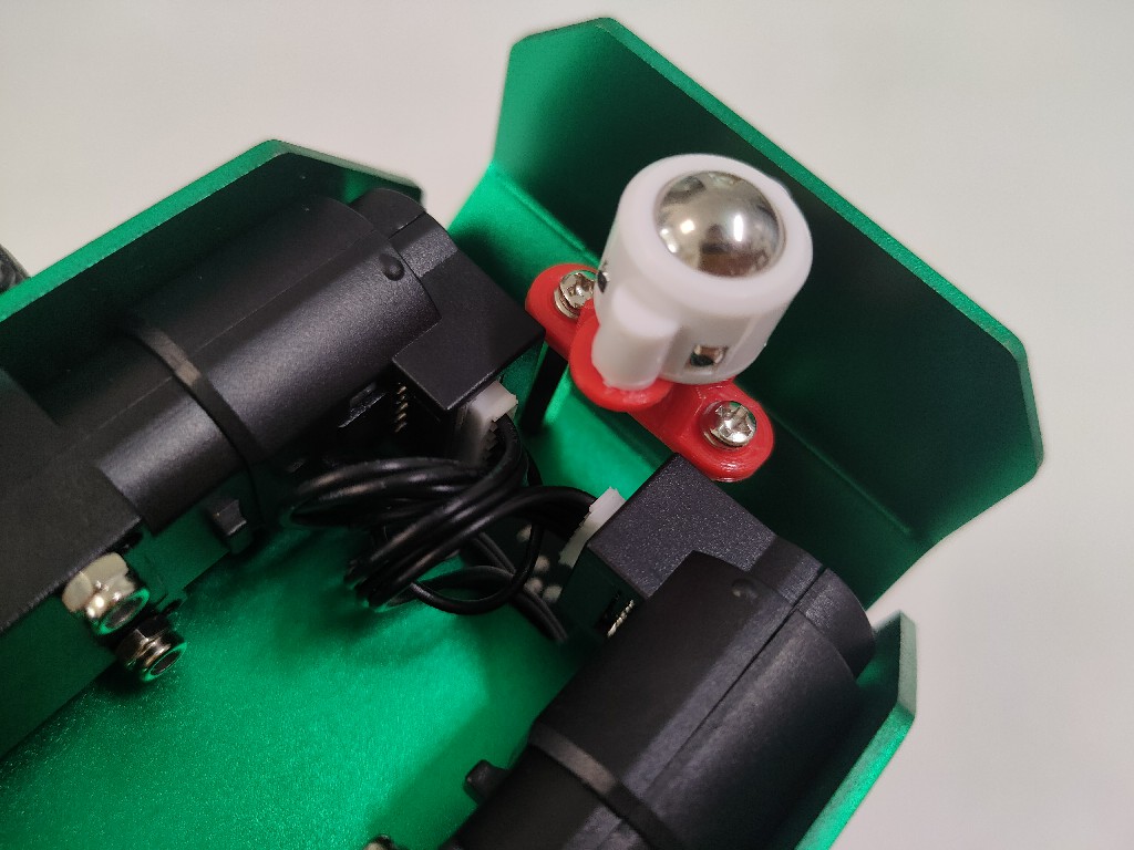
(2)Install universal wheels
Using screws and spacers, secure the universal wheel to the end of the copper post:
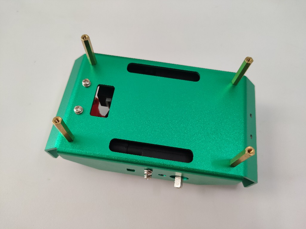
Install the controller to support the copper pillars:
Materials required:
The fixing holes of the chassis have their own threads, and the four copper pillars can be tightened directly:
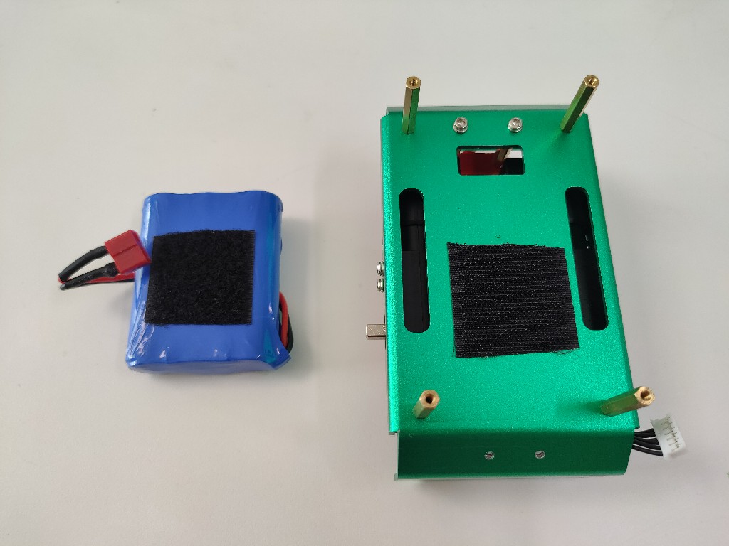
Install the power battery:
Materials required:
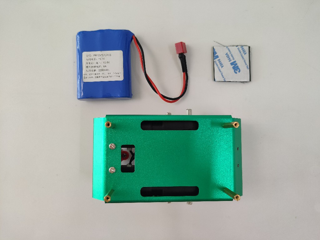
(1)Install the Magic Sticker
Peel off the double-sided tape of the velcro and stick it on the chassis and battery separately:
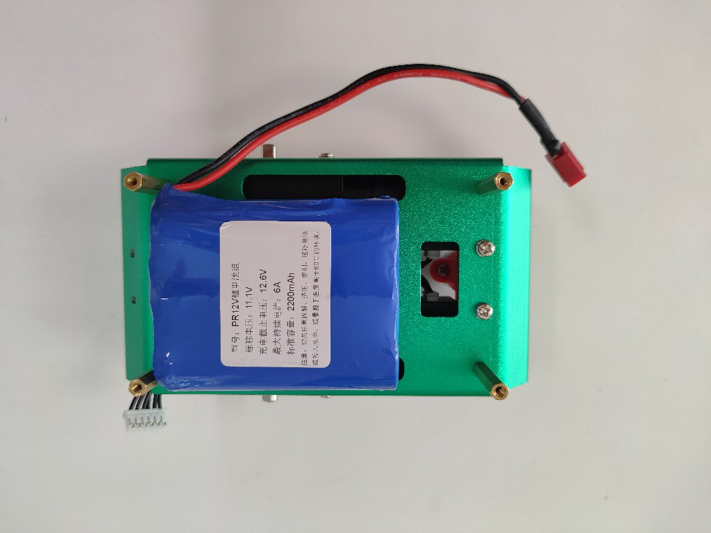
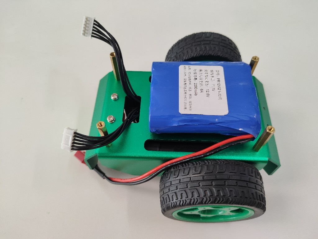
(2)Install the battery
Fix the battery on the chassis by Velcro, the battery should be as close to the left side as possible, and ensure that the center of gravity is on the bottom shaft of the motor:
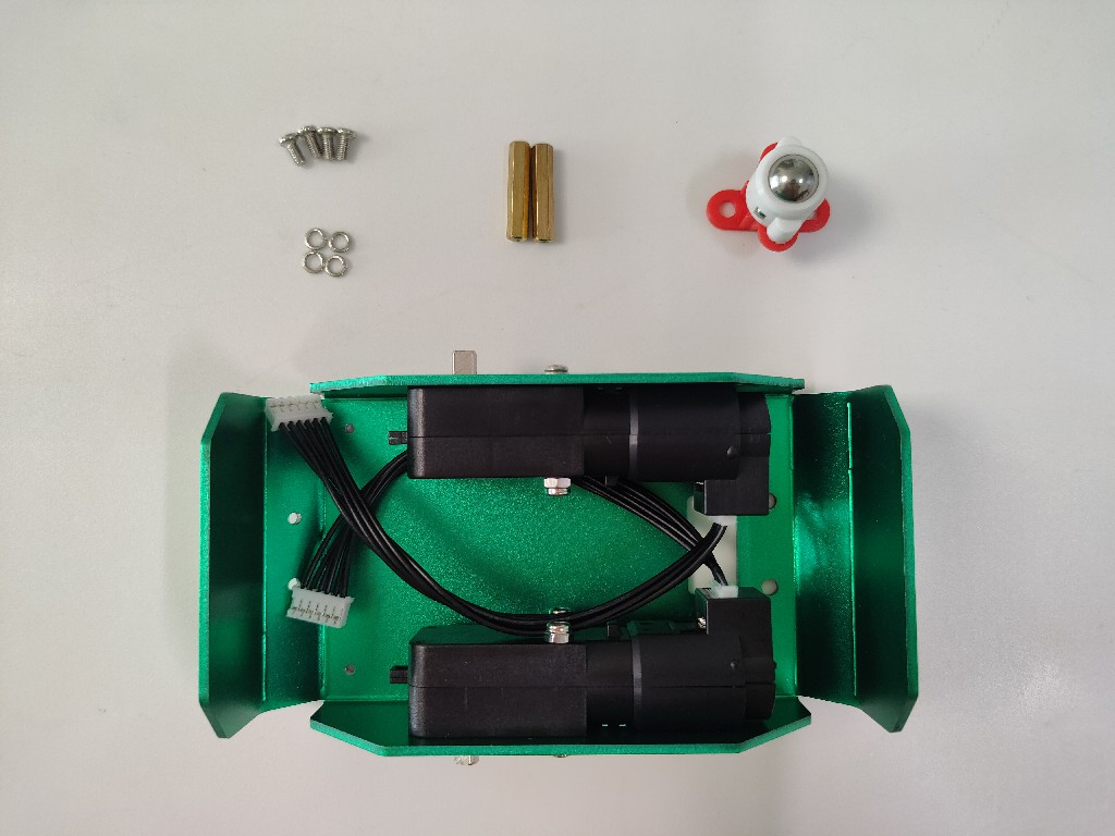
Install the wheels:
Materials required:
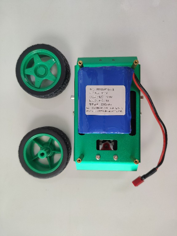
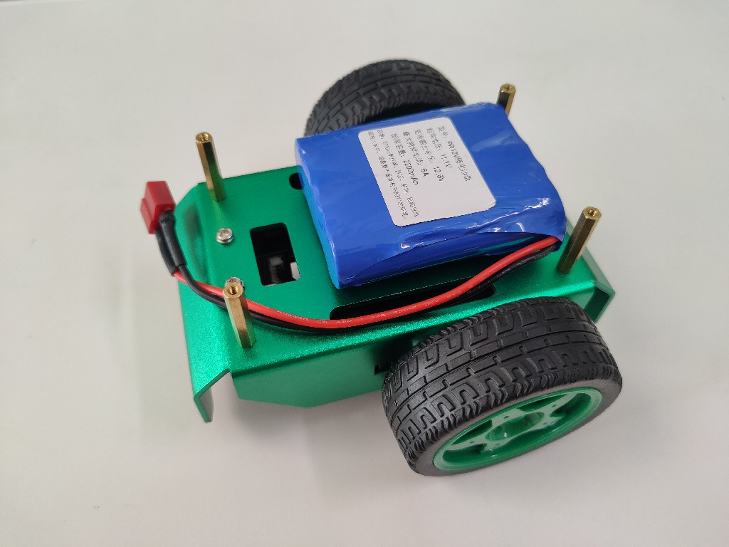
(1)Install the Wheels
Press the two wheels separately on the motor axles on both sides of the chassis:
Hint
Pay attention to the force to avoid damaging the motor.
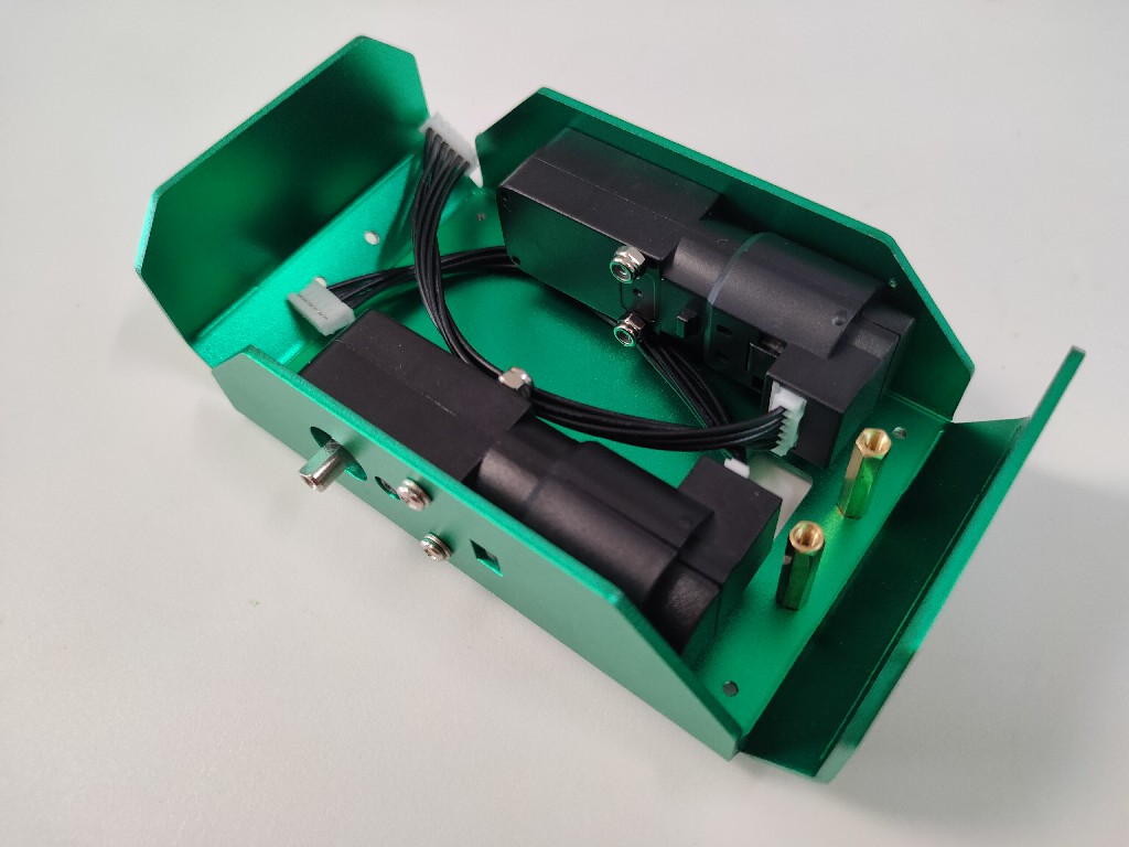
(2)Sort out the motor line
Thread the cables of the two motors out of the chassis to facilitate subsequent wiring, and pay attention to the motor wiring should be firmly connected to avoid poor contact:
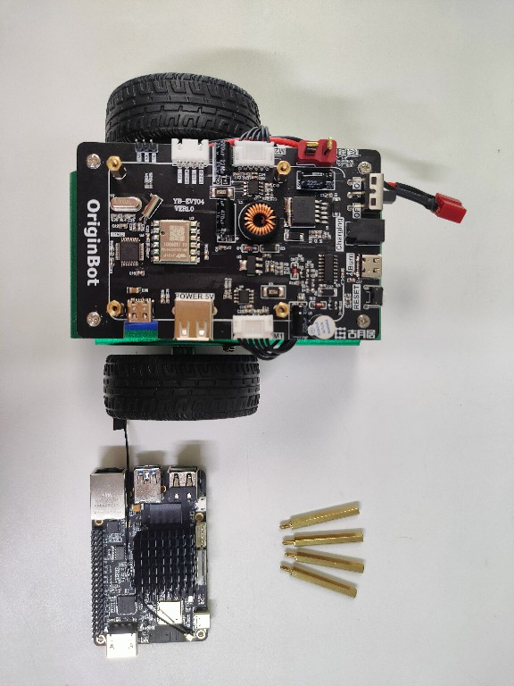
Install the controller board
Install the upper layer of the controller to support the copper pillar
Materials required:
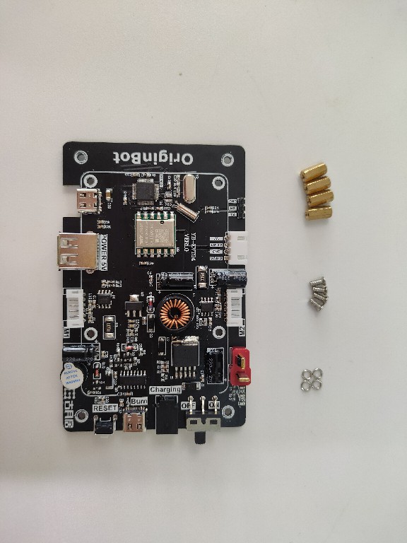
Place the copper pillar in the front hole of the controller and tighten it from the reverse side using screws and spacers:
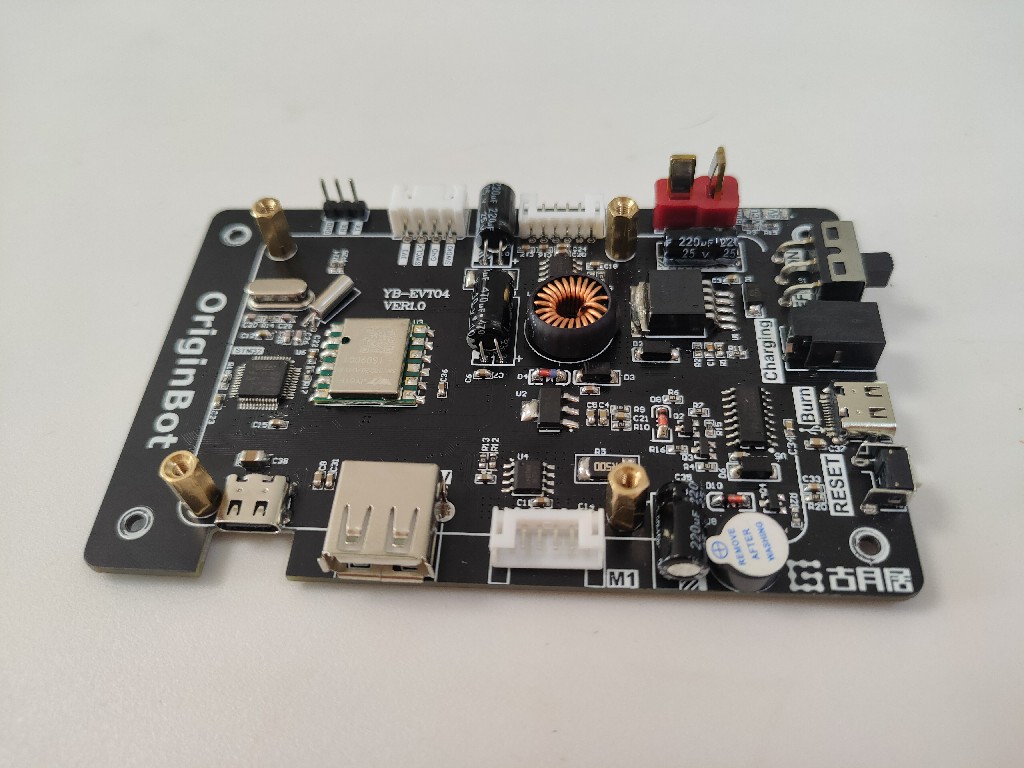
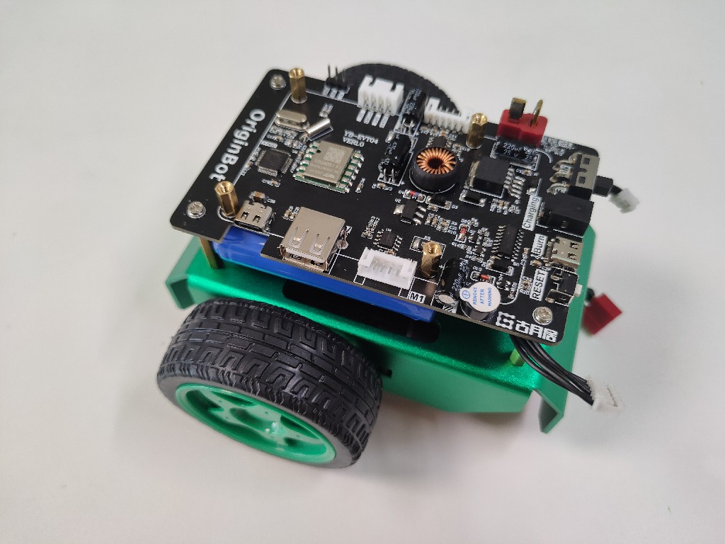
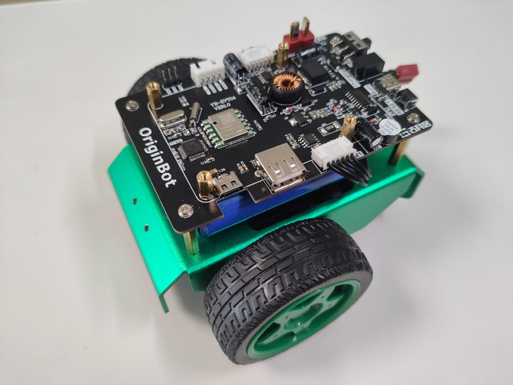
Install the controller board
Materials required:
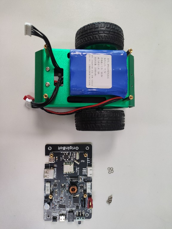
Use screws and spacers to secure the controller to the 4 supporting copper posts of the chassis:
Connect the motor cables
Connect the previously routed motor cables to the corresponding ports of the controller:
Hint
- Pay attention to the serial number of the motor interface, the left motor is connected to control the left side interface, and the right motor is connected to control the right side interface;
- When plugging in the white port, it is recommended to press and hold the connector on the controller side with the other hand to avoid excessive force;
- At this time, do not connect the battery power cord to avoid subsequent misoperation;
Install the processor board
Install the processor heatsink and antenna
Hint
The RDK X3 Compared with Sunrise X3 pi, the WIFI capability is enhanced, and there is no need to connect an external WIFI antenna here.
Materials required:
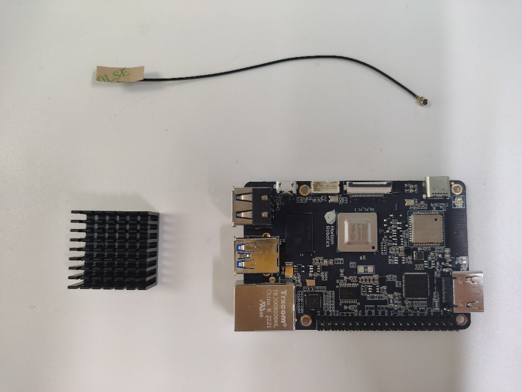
Peel off the blue sticker on the back of the heatsink and attach the included white adhesive to the core SoC of RDK X3, and then press the antenna to connect it to the corresponding connector of the board.
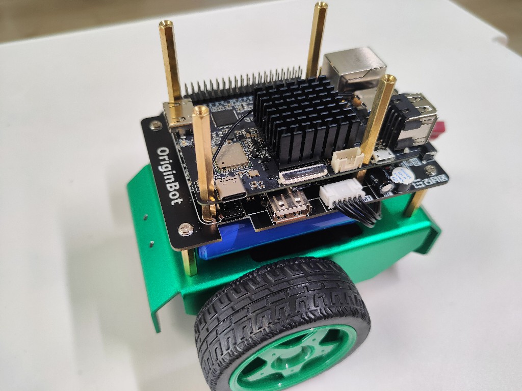
Install the processor board
(1) AI vision version
Materials required:
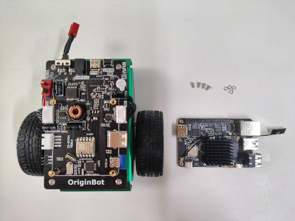
If you don't need to install a lidar, you can mount the RDK X3 directly to the supporting copper pillar on the controller with screws and spacers:
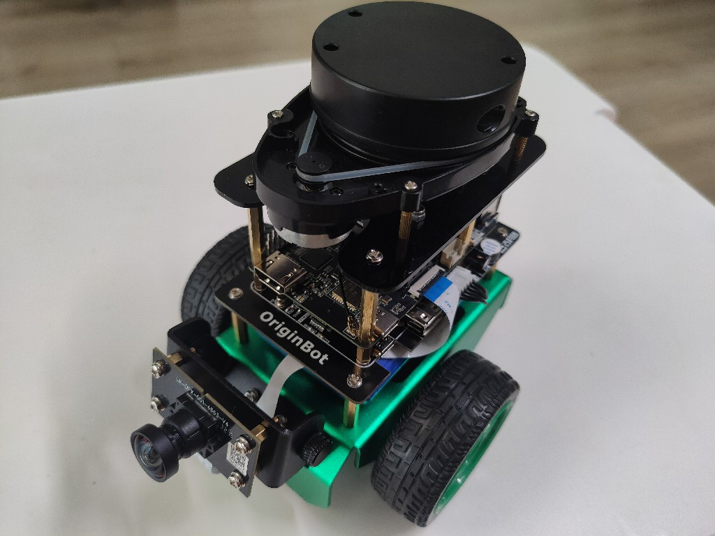
(2)Autonomous navigation version
Materials required:
If you need to install the lidar, you can use 4 copper pillars to mount the RDK X3 to the controller's support copper pillars:
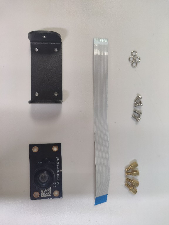
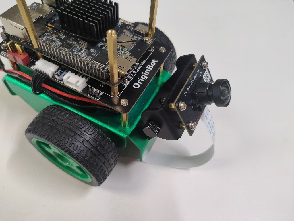
Attach the camera
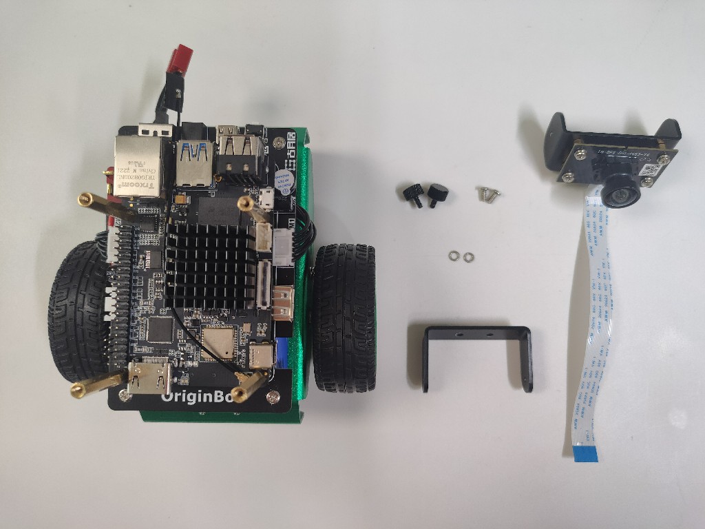
Install the camera module
Materials required:
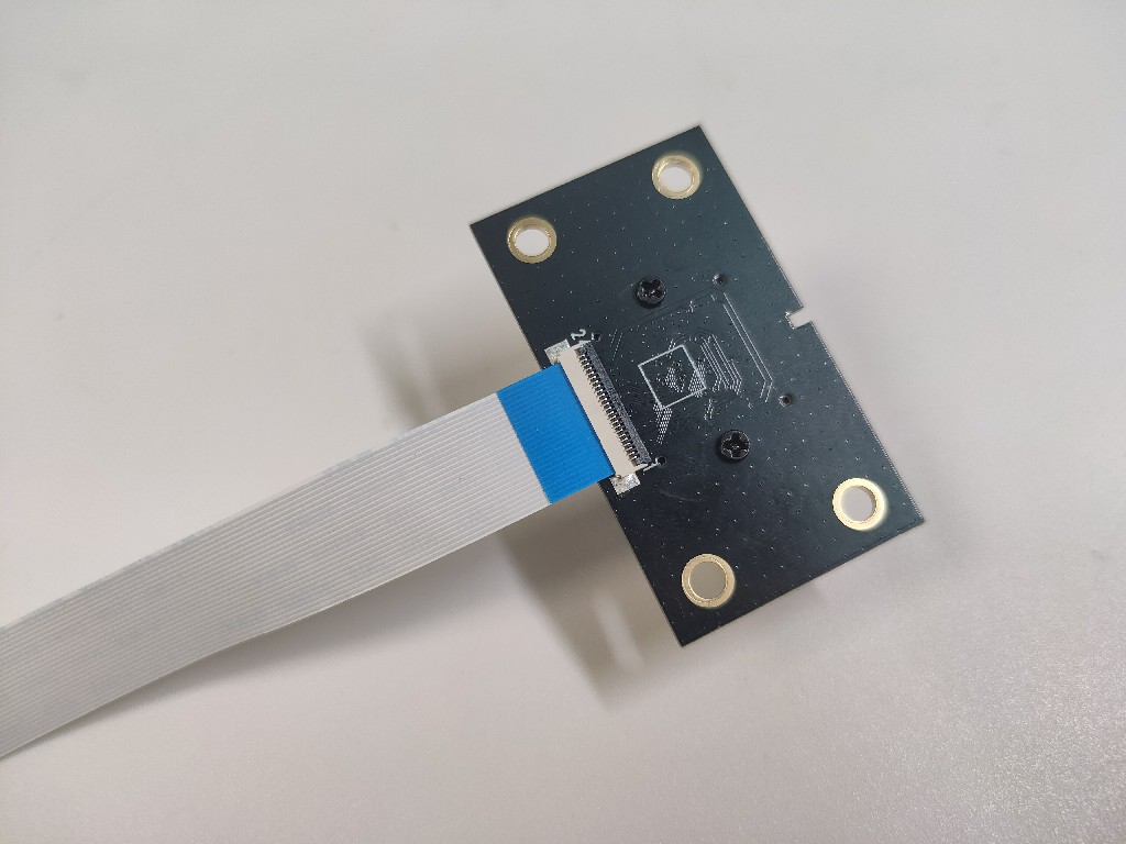
(1)Connect the camera cable
Gently pick the black buckle on the back of the camera, insert a section of the cable into the port, and then tap the black buckle to complete the connection:
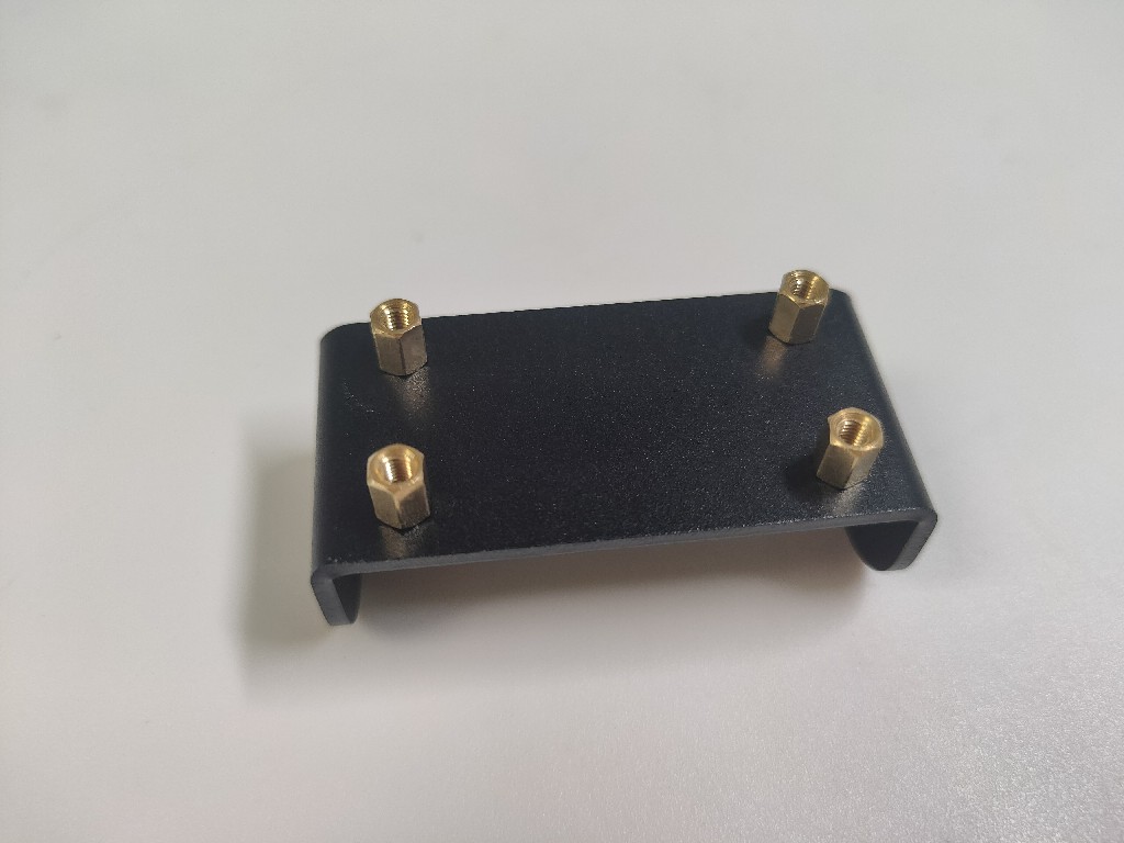
(2)Install the camera mount
The camera mount has its own threads, and the 4 copper pillars can be tightened directly:
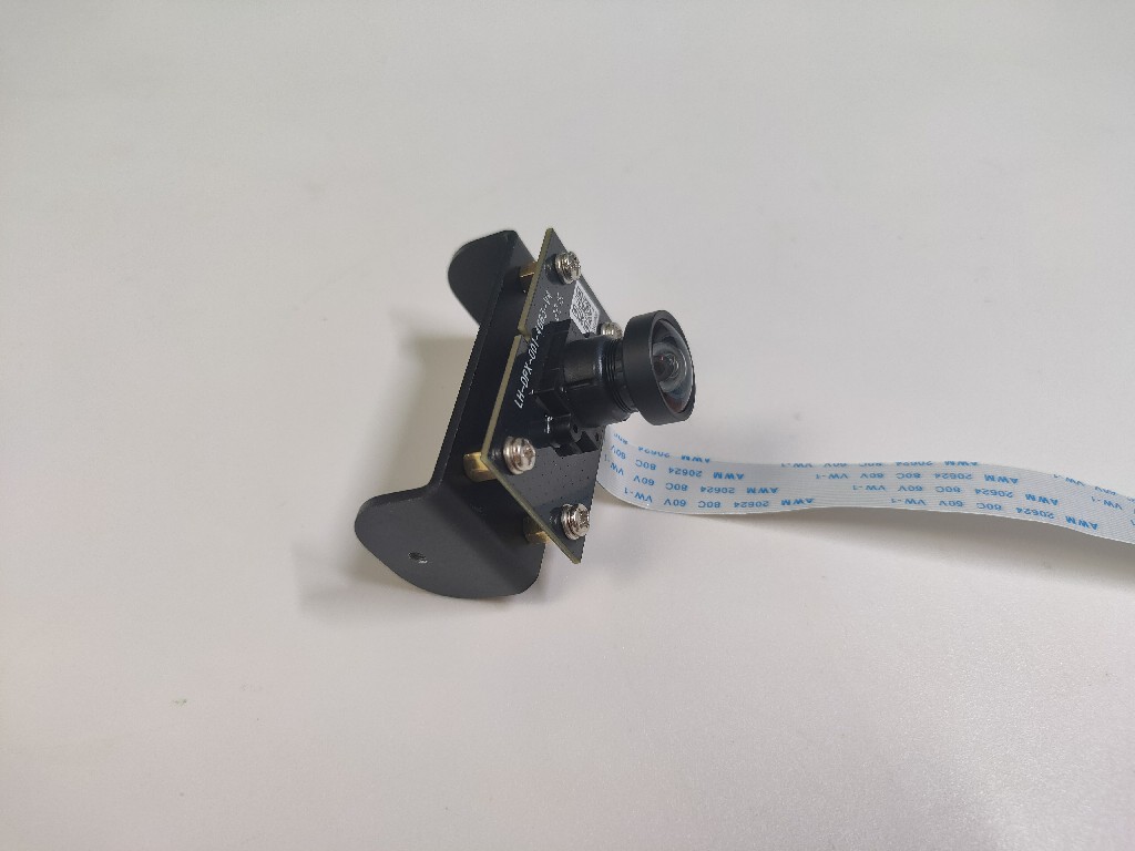
(3)Install the camera
Using four screws and spacers, mount the camera module on the mount:
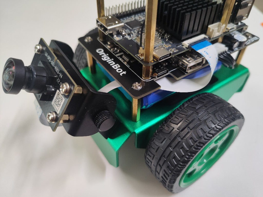
Attach the camera
Materials required:
(1)Install the camera holder
The chassis has its own threads on the mounting holes, and the camera holder is mounted to the chassis using two screws and spacers:
(2)Install the camera mount
Attach the camera holder to the camera mount using two hand screws:
Hint
There needs to be enough friction between the camera mount and the camera holder. If the camera cannot fix the Angle, you can use your hand to break the camera holder outwards and then install the camera mount.
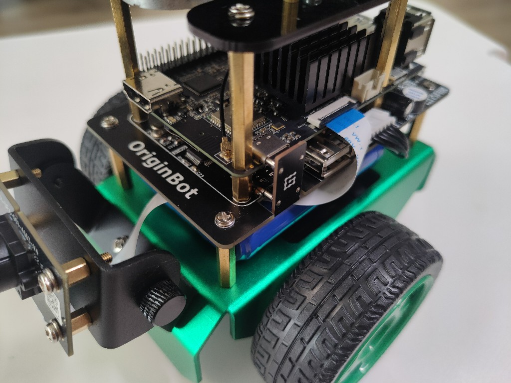
(3)Connect the camera data cable
Thread the camera cable between the chassis controller and the battery and connect it to the RDK X3's connector:
Danger
It is forbidden to plug and unplug the camera cable when the power is on, as it will damage the camera.
Install lidar
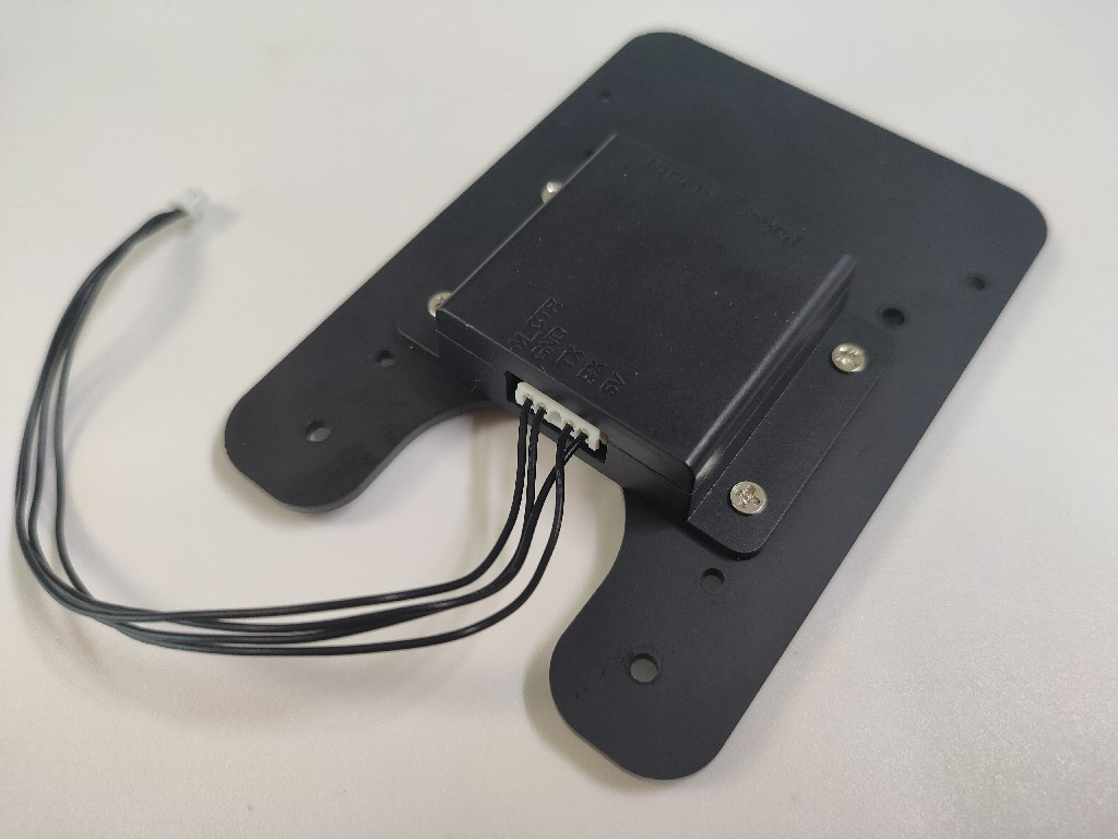
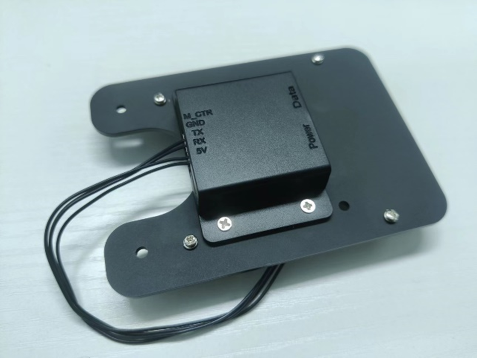
Install the lidar serial port module
Materials required:
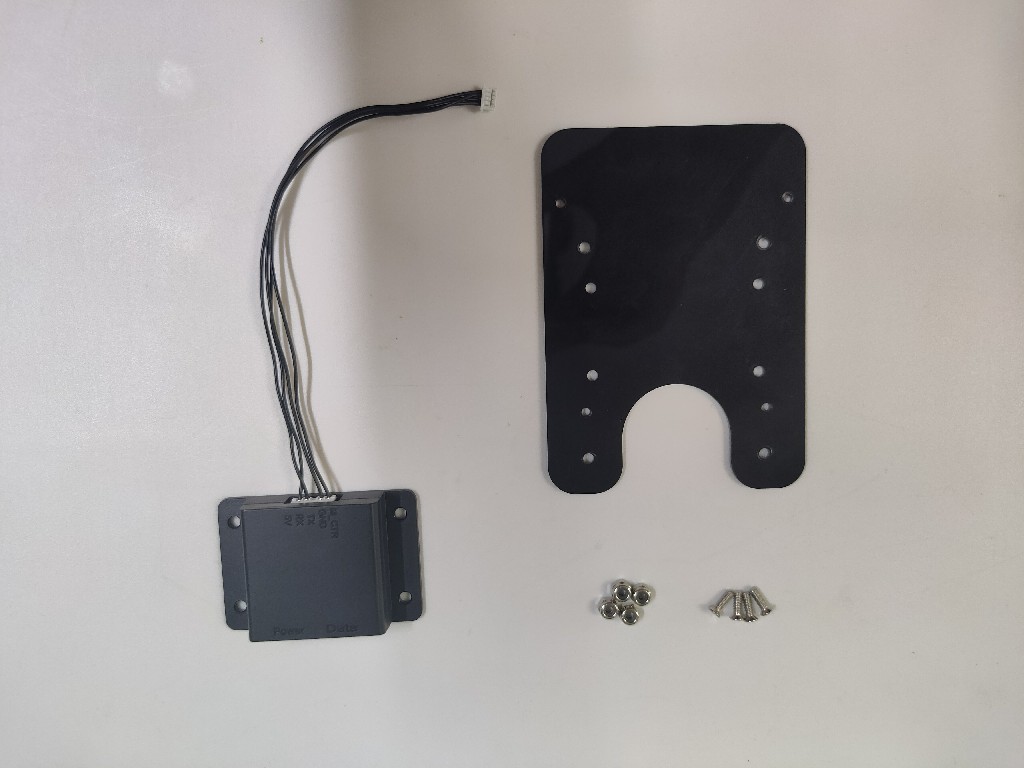
Peel off the protective film of the acrylic sheet and use 4 screws to mount the serial module of the lidar to the acrylic sheet:
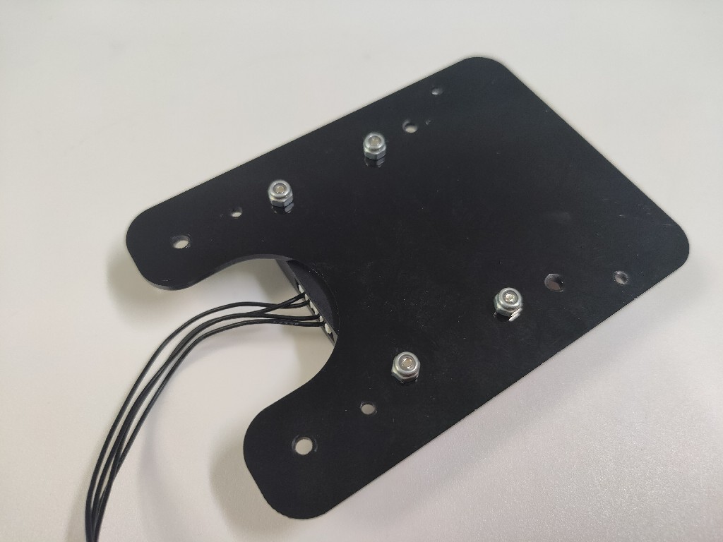
On the other side of the acrylic sheet, using four non-slip nuts, tighten the screws:
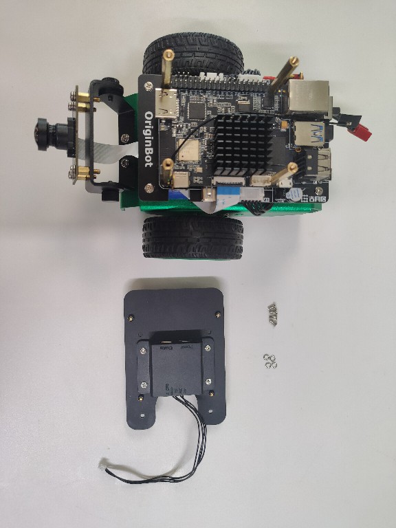
Install the lidar mount
Materials required:
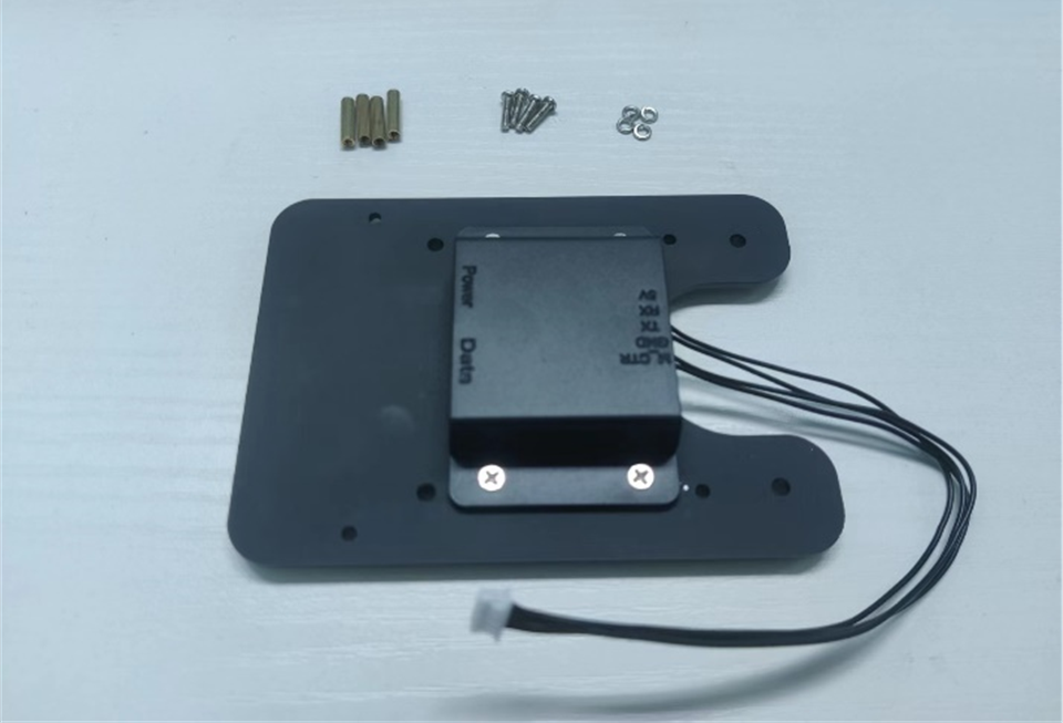
Thread the four copper pillars through the corresponding holes in the acrylic plate:
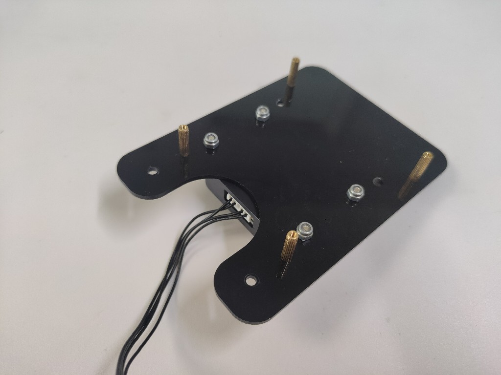
The other side is secured by four non-slip nuts and the copper pillar is tightened:
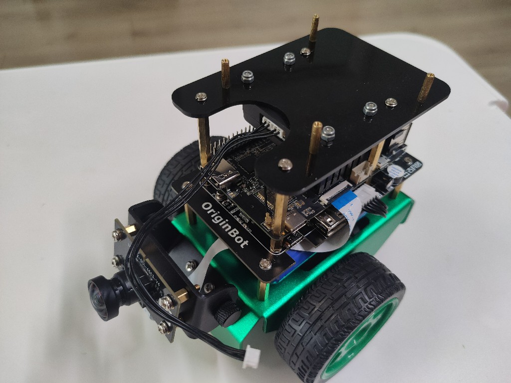
Install lidar acrylic plates
Materials required:
Using four screws and spacers, mount the acrylic sheet to the ends of the four copper pillars on the RDK X3:
Install the lidar
Materials required:
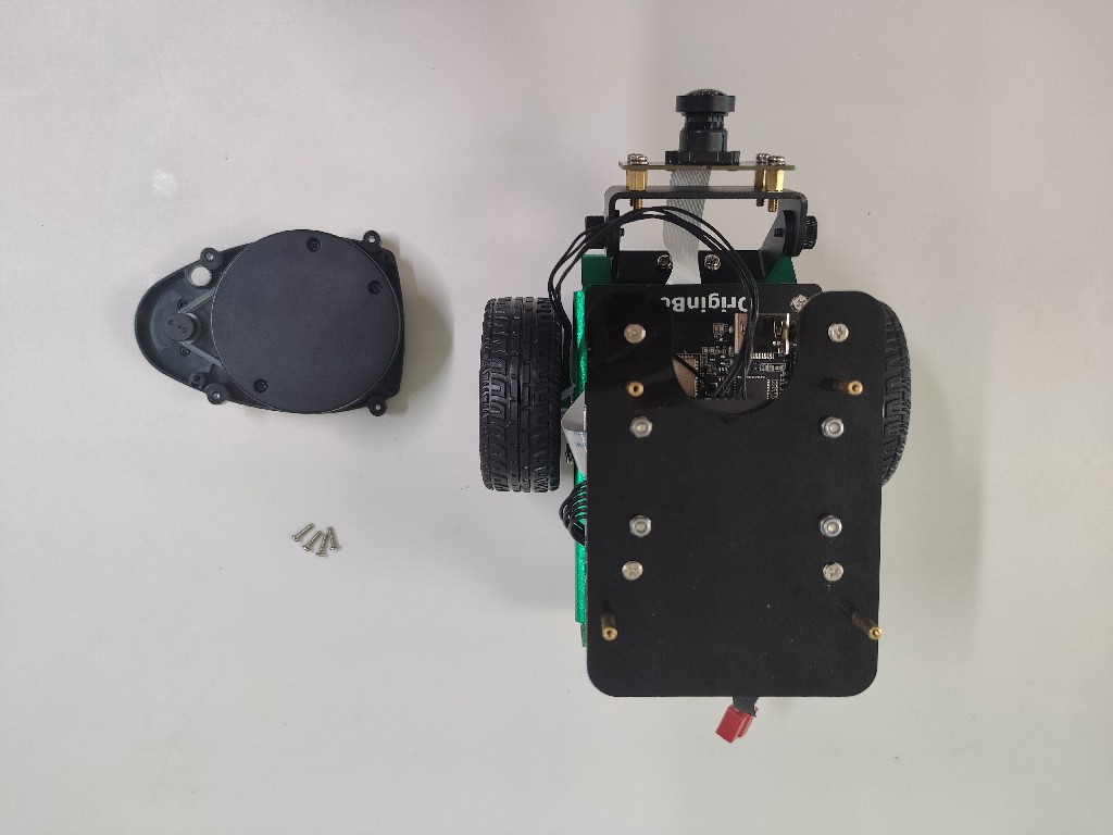
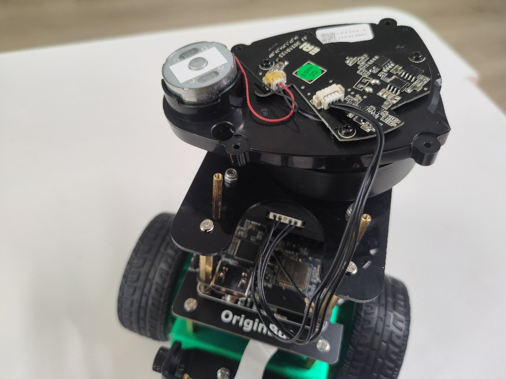
(1)Connect the lidar serial port cable
Connect the serial cable of the lidar serial module to the corresponding interface on the back of the lidar:
(2)Install the lidar
Use four screws to secure the lidar to the supporting copper posts of the acrylic sheet:
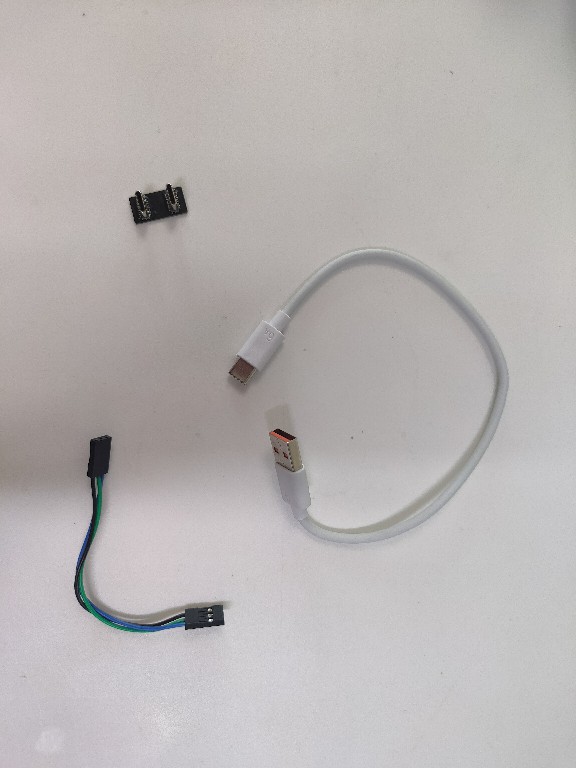
Connect the cables
Materials required:
(1)Connect the power supply module
RDK X3 is powered by the controller through the TypeC port, and the TypeC power supply module is used to connect the power output of the controller and the power input of RDK X3.
Hint
When plugging and unplugging TypeC power supply modules, use caution to avoid damaging the chip pins.
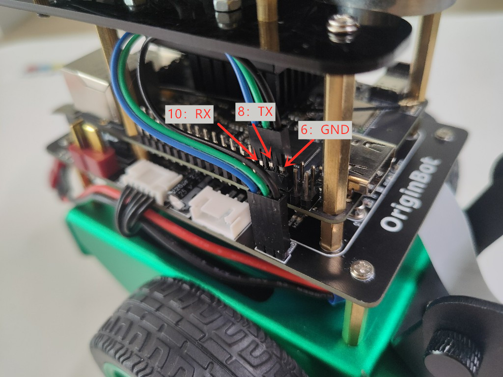
(2)Connect the serial communication line
Use the serial communication cable to connect the communication interface of the controller and the RDK X3:
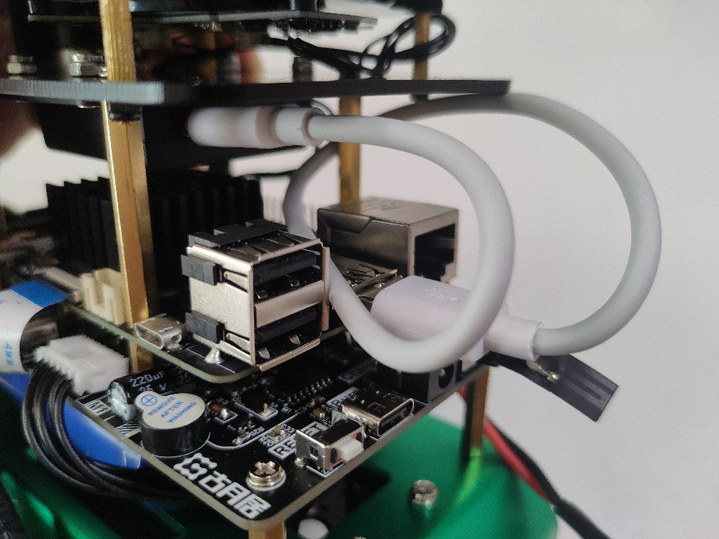
(3)Connect the lidar communication line
The original TypeC data cable of the lidar is long, you can use the short cable in the kit, one side is connected to the USB port of RDK X3, and the other side is connected to the TypeC port of the lidar serial port module:
(4)Connect the main power cord
Check that all parts of the robot have been installed correctly according to the operation steps, and that the control switch is in the "OFF" state, and connect the main power cord of the battery to the controller:
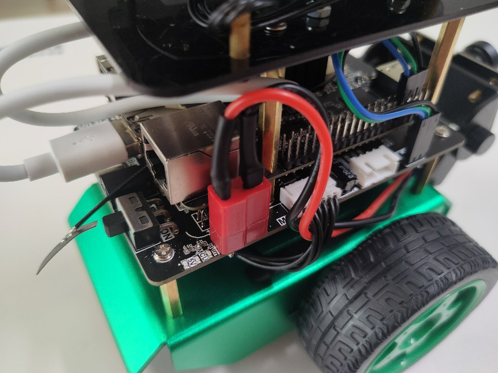
Hint
The power socket is tight and close to the RDK X3, so please install and insert it carefully. Placing the two flat parts of the T-plug close to the socket will make it easier to plug in.
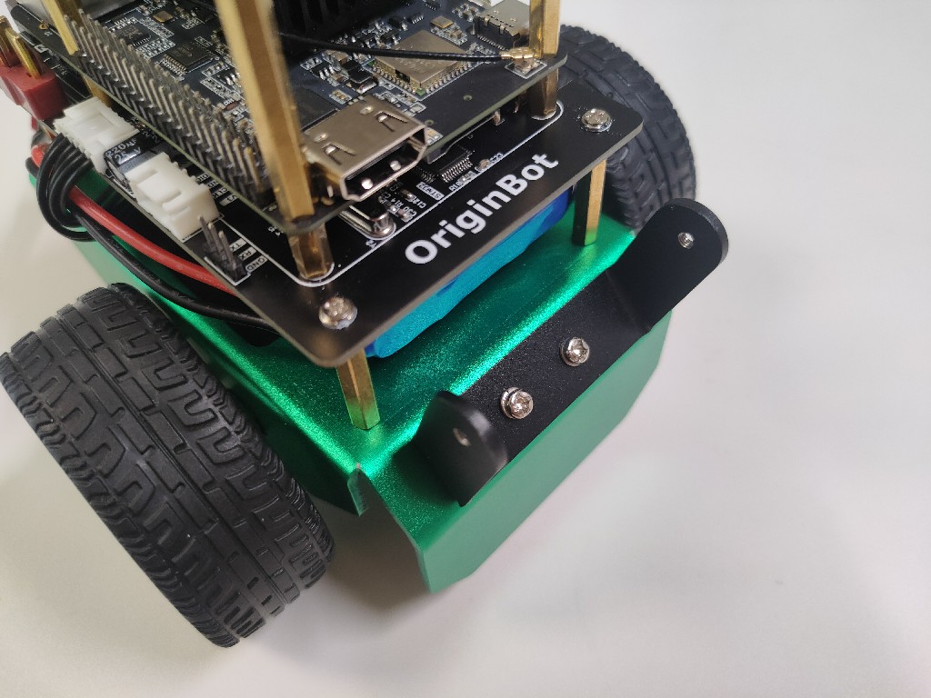
Install license plate and lidar sticker (optional)
Materials required:
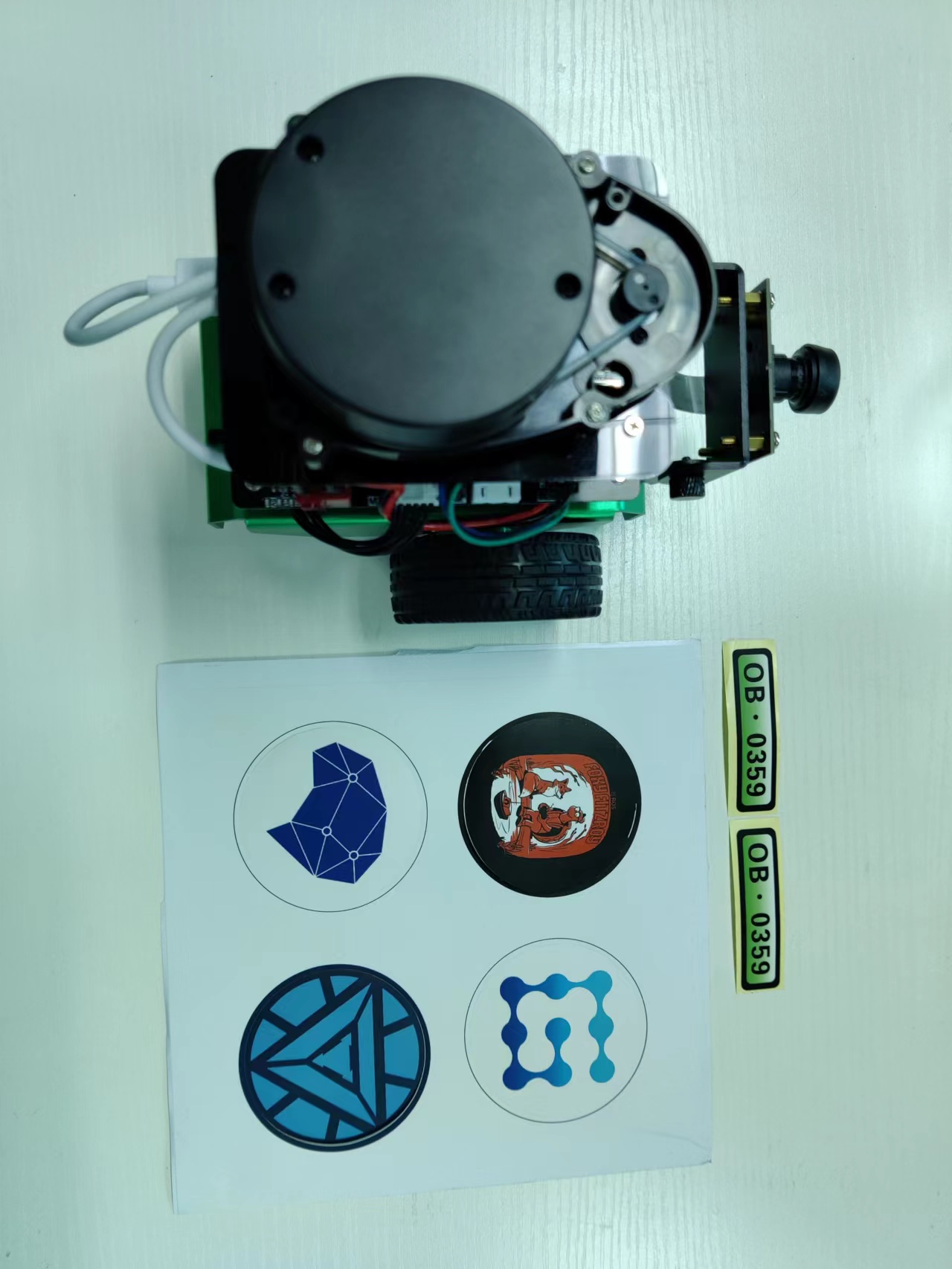
Paste the license plate
Paste the uniquely numbered stickers included in the kit to the front and rear sides of the chassis as needed.

Paste the lidar sticker
Attach the lidar sticker included in the kit to the top of the lidar as needed.
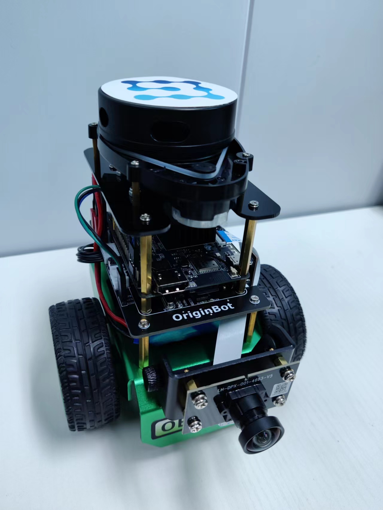
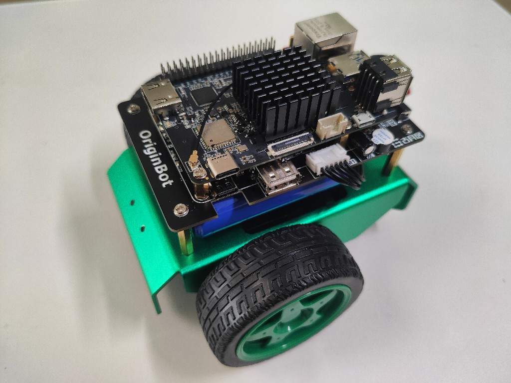
At this point, the installation of OriginBot is complete.